- 您现在的位置:买卖IC网 > Sheet目录624 > FSBB15CH60C (Fairchild Semiconductor)IC POWER MOD SPM 600V SPM27CC
�� �
�
�Mini� DIP� (SPM3)� Application� Note� (2012-07-09)�
�ignored� due� to� its� large� value.�
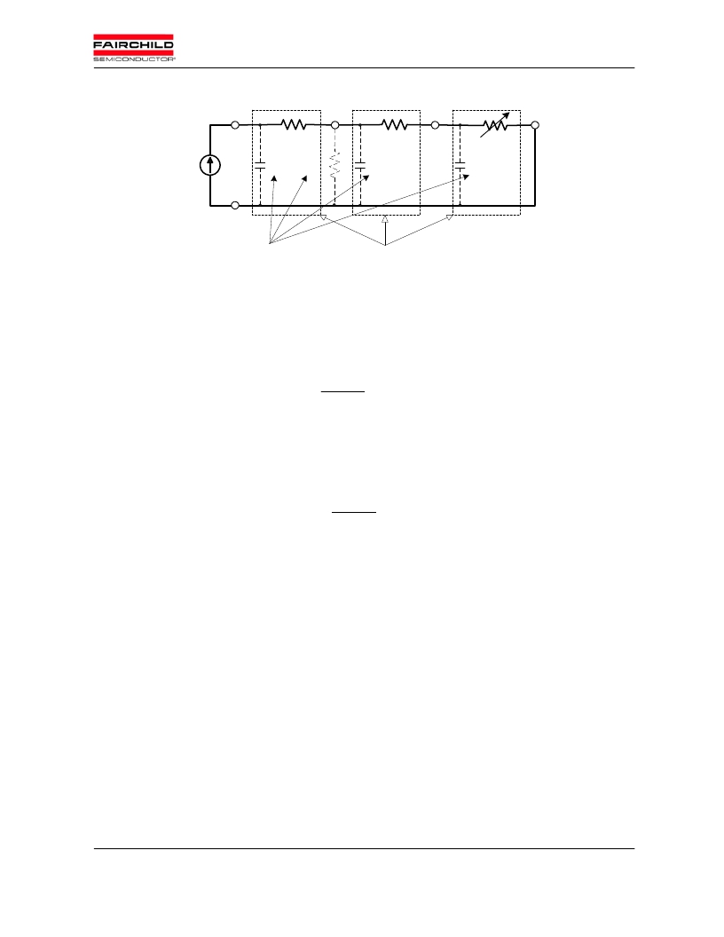
�T� j�
�R� θjc�
�T� c�
�R� θch�
�T� h�
�R� θha�
�T� a�
�P� D�
�C� jc�
�R� θca�
�C� ch�
�C� ha�
�B� eing� ig� no� red�
�Transient� im� p� ed� ance�
�o� f� each� sectio� n�
�Figure� 9.1� Transient� thermal� equivalent� circuit� with� a� heatsink.�
�The� thermal� resistance� of� the� SPM� is� defined� in� the� following� equation,�
�R� ?� jc� ?�
�T� j� ?� T� c�
�P� D�
�(9.11)�
�where� R� ?� jc� (� o� C/W)� is� the� junction-to-case� thermal� resistance,� and� P� D� (W),� T� j� (� o� C)� and� T� c� (� o� C)� are� power�
�dissipation� per� device,� junction� temperature� and� case� reference� temperature,� respectively.� By� replacing� T� c�
�with� T� a� (ambient� temperature),� the� junction-to-ambient� thermal� resistance� R� ?� ja� can� be� obtained� as� following,�
�R� ?� ja� ?�
�T� j� ?� T� a�
�P� D�
�(9.12)�
�where� R� ?� ja� indicates� the� total� thermal� performance� of� the� SPM� including� the� heat� sink.� Basically� R� ?� ja� is�
�a� serial� summation� of� various� thermal� resistances,� R� ?� jc� ,� R� ?� ch� and� R� ?� ha� .�
�R� ?� ja� ?� R� ?� jc� ?� R� ?� ch� ?� R� ?� ha�
�(9.13)�
�where� R� ?� ch� is� contact� thermal� resistance� due� to� the� thermal� grease� between� the� package� and� the� heat�
�sink,� and� R� ?� ha� is� heat� sink� thermal� resistance,� respectively.� From� the� equation� (9.13),� it� is� clear� that�
�minimizing� R� ?� ch� and� R� ?� ha� is� an� essential� application� factor� to� maximize� the� power� carrying� ability� of� the� SPM�
�as� well� as� the� minimizing� of� R� ?� jc� itself.� An� infinite� heat� sink� will� result� if� R� ?� ch� and� R� ?� ha� are� reduced� to� zero� and�
�the� case� temperature� T� c� is� locked� at� the� fixed� ambient� temperature� T� a� .� Usually,� the� value� of� R� ?� ch� is�
�proportional� to� the� thermal� grease� thickness� and� governed� by� the� skill� at� the� assembly� site,� while� R� ?� ha� can� be�
�handled� to� some� extent� by� selecting� an� appropriate� heat� sink.�
�In� practical� operation,� the� power� loss� P� D� is� cyclic� and� therfore� the� transient� RC� equivalent� circuit� shown�
�in� Fig.� 9.1� should� be� considered.� For� pulsed� power� loss,� the� thermal� capacitance� effect� delays� the� rise� in�
�junction� temperature,� and� thus� permits� a� heavier� loading� of� the� SPM.� Figure� 9.2� shows� the� normalized�
�?� 2008�
�FAIRCHILD� SEMICONDUCTOR� -� Smart� Power� Module�
�45�
�发布紧急采购,3分钟左右您将得到回复。
相关PDF资料
FSBB15CH60F
MODULE SPM 600V SPM27-CA
FSBB20CH60CL
SMART POWER MODULE 20A SPM27-CB
FSBB20CH60CT
MODULE ADV MOTION SPM SPM27-CC
FSBB20CH60C
MODULE MOTION-SPM 600V SPM27-CC
FSBB20CH60SL
MODULE SPM 600V 20A SPM27-CA
FSBB30CH60F
IC SMART PWR MODULE SPM27-EA
FSBF10CH60BTL
MODULE SPM 600V 10A 3PH SPM27-JB
FSBF10CH60BT
MODULE SPM 600V 10A 3PH SPM27-JA
相关代理商/技术参数
FSBB15CH60C
制造商:Fairchild Semiconductor Corporation 功能描述:Transistor
FSBB15CH60F
功能描述:IGBT 晶体管 600V SPM RoHS:否 制造商:Fairchild Semiconductor 配置: 集电极—发射极最大电压 VCEO:650 V 集电极—射极饱和电压:2.3 V 栅极/发射极最大电压:20 V 在25 C的连续集电极电流:150 A 栅极—射极漏泄电流:400 nA 功率耗散:187 W 最大工作温度: 封装 / 箱体:TO-247 封装:Tube
FSBB20CH60
功能描述:IGBT 模块 HIGH_POWER
RoHS:否 制造商:Infineon Technologies 产品:IGBT Silicon Modules 配置:Dual 集电极—发射极最大电压 VCEO:600 V 集电极—射极饱和电压:1.95 V 在25 C的连续集电极电流:230 A 栅极—射极漏泄电流:400 nA 功率耗散:445 W 最大工作温度:+ 125 C 封装 / 箱体:34MM 封装:
FSBB20CH60B
功能描述:IGBT 模块 600V -20A 3-phase RoHS:否 制造商:Infineon Technologies 产品:IGBT Silicon Modules 配置:Dual 集电极—发射极最大电压 VCEO:600 V 集电极—射极饱和电压:1.95 V 在25 C的连续集电极电流:230 A 栅极—射极漏泄电流:400 nA 功率耗散:445 W 最大工作温度:+ 125 C 封装 / 箱体:34MM 封装:
FSBB20CH60BT
功能描述:IGBT 模块 600V -20A 3-phase RoHS:否 制造商:Infineon Technologies 产品:IGBT Silicon Modules 配置:Dual 集电极—发射极最大电压 VCEO:600 V 集电极—射极饱和电压:1.95 V 在25 C的连续集电极电流:230 A 栅极—射极漏泄电流:400 nA 功率耗散:445 W 最大工作温度:+ 125 C 封装 / 箱体:34MM 封装:
FSBB20CH60C
功能描述:IGBT 模块 600V 20A SPM
RoHS:否 制造商:Infineon Technologies 产品:IGBT Silicon Modules 配置:Dual 集电极—发射极最大电压 VCEO:600 V 集电极—射极饱和电压:1.95 V 在25 C的连续集电极电流:230 A 栅极—射极漏泄电流:400 nA 功率耗散:445 W 最大工作温度:+ 125 C 封装 / 箱体:34MM 封装:
FSBB20CH60CL
功能描述:IGBT 模块 20A, Motion-SPM
RoHS:否 制造商:Infineon Technologies 产品:IGBT Silicon Modules 配置:Dual 集电极—发射极最大电压 VCEO:600 V 集电极—射极饱和电压:1.95 V 在25 C的连续集电极电流:230 A 栅极—射极漏泄电流:400 nA 功率耗散:445 W 最大工作温度:+ 125 C 封装 / 箱体:34MM 封装:
FSBB20CH60CT
功能描述:IGBT 模块 600V 20A SPM
RoHS:否 制造商:Infineon Technologies 产品:IGBT Silicon Modules 配置:Dual 集电极—发射极最大电压 VCEO:600 V 集电极—射极饱和电压:1.95 V 在25 C的连续集电极电流:230 A 栅极—射极漏泄电流:400 nA 功率耗散:445 W 最大工作温度:+ 125 C 封装 / 箱体:34MM 封装: